Embedded Protocol UART
UART (Universal Asynchronous Receiver/Transmitter) is a standard communication protocol used for serial communication between devices. It’s commonly employed in embedded systems for communication between microcontrollers, sensors, and other peripheral devices.
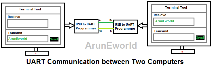
In the context of embedded systems, UART is often used as a hardware communication protocol, enabling devices to transmit and receive data serially. The UART communication involves two pins: TX (transmit) and RX (receive).
- It’s is full-duplex communication
- UART contains a shift register
- which is the fundamental method of conversion between serial and parallel forms.
- Type of Communication: Asynchronous (No clock).
- Rule: The transmitter and receiver should same baud rate. Data format and transmission speed are configurable.
- UART Uses serial communication over a computer or peripheral device serial port. (Electronics Devices).
UART Speed (Baud Rate)
UART supports many baud rate are 300, 600, 1200, 2400, 4800, 9600, 19200, 38400, 57600, 74880, 115200, 230400, 256000, 460800, 921600, 1843200, 3686400.
Time Consume for each Baud Rate
| Baud Rate | Configurations | Time Calculation | Bytes/ Per Seconds |
|---|---|---|---|
| 9600 | 1 start Bit. 8 data bits. 1 stop bit. | Each bit will take 1/9600= 104.2us. So here using 10 bits for 1byte transmissions. Than 9600/10 = 960Bytes can able to send in one second. | 960Bytes |
| 19200 | 1 start Bit. 8 data bits. 1 stop bit. | Each bit will take 1/19200= 52us. So here using 10 bits for 1byte transmissions. Then 19200/10 = 1920Bytes can able to send in one second. | 1920Bytes |
| 57600 | 1 start Bit. 8 data bits. 1 stop bit. | Each bit will take 1/57600= 17.36us. So here using 10 bits for 1byte transmissions. Then 57600/10 = 5760Bytes can able to send in one second. | 5760Bytes |
UART Definition
- Auto baud rate
- DUART (Dual UART)
- Parity error
- Overrun error
- TX register: TX shift Register (TSR) à in PIC16F8X
- RX resister: RX Shift Register (RSR) à in PIC16F8X
- 1 Start bit, (LSB to MSB) 8bit data, 1-parity check bit, 1stop bit,
UART Packet Format
- The least significant bit (LSB) is always the first bit transmitted, and the most significant bit (MSB) is transmitted last.
- For example, in the binary representation of decimal 5, the LSB is 1, and the MSB is 0, making the binary form 0b00000101.
- Here LSB will be first and followed by MSB like 10100000.


Start Bit
- The UART data transmission line typically maintains a high voltage level when not actively transmitting data. To start the transfer of data, the transmitting UART pulls the transmission line from high to low for one clock cycle. When the receiving UART detects the high to low voltage transition, it begins reading the bits in the data frame at the frequency of the baud rate.
- The start bit is logically low. The start bit signals the receiver that a new character is coming.
Data Frame
- The data frame contains the actual data being transferred. It can be 5 bits up to 8 bits long if a parity bit is used. If no parity bit is used, the data frame can be 9 bits long. In most cases, the data is sent with the least significant bit first.
Parity Bit
Parity, indicating evenness or oddness, is crucial as the receiving UART uses it to detect changes during transmission. These changes can be caused by factors like electromagnetic radiation or mismatched baud rates. After processing the data frame, the UART counts 1 bit, assessing if the total is even or odd based on the parity bit (0 for even, 1 for odd). Consequently, a match assures error-free transmission, but discrepancies indicate alterations in the data frame.
UART Interrupts
- Transmitter Interrupt
- Receiver Interrupts
- Wakeup Interrupts
- Error Interrupts (Parity errors (PE), Frame errors (FE), Break Detect errors (BRKDT), Overrun errors (OE), Underrun ErrorBit errors (BE))
Wake Up Interrupts
Some advanced controllers have this feature. You need to set wakeup interrupt in SCI register. Setting this bit enables the SCI to generate a wakeup interrupt and thereby exit the low-power mode. If enabled, the wake-up interrupt is asserted when the local low-power mode is requested while the receiver is busy or if a low level is detected on the SCIRX pin during low-power mode.
UART Error
- Framing Error: Occurs when the designated start and stop bits are not found. If the data line isn’t in the expected state during the stop bit, a framing error occurs.
- Underrun Error: Happens when the UART transmitter completes sending a character, and the transmit buffer is empty. In asynchronous mode, it signifies that there is no remaining data to be transmitted.
- Overrun Error: Occurs when a new byte arrives before the previous one is read from the UART’s receive buffer. This is mainly due to the CPU taking time to service the UART interrupt for removing characters.
- Parity Error: Happens when the number of 1 bits disagrees with the specified parity bit.This error occurs only when the system enables parity checking, as it is an optional feature. It can identify a single-bit error but can’t detect two or more bits’ errors.
- Break Condition: Occurs when the receiver input stays at the space level for longer than a specified duration, typically exceeding a character time. Setting a break enables the detection of interruptions in registers and generates an error interrupt if the SCIRX pin detects a break condition.
Stop Bit
- To signal the end of the data packet, the sending UART drives the data transmission line from a low voltage to a high voltage for at least two-bit duration.
UART ICS
- WD1402A is the first single-chip UART on general sale. Introduced about 1971.
- Compatible chips included the Fairchild TR1402A and the general instruments AY-5-1013.
- What is the speed of the 8250 UART? : The 8250 UART has one character buffer for the receiver and the transmitter each, which meant that communications software performed poorly at speed above 9600bits/sec, especially it operating under a multitasking system or if handling interrupts from disk controllers.
UART Advantage & Disadvantages
| Advantages | Disadvantage |
|---|---|
| Only two wires interface. No clock signal is necessary. Error checking Feature allows: Has a parity bit check The structure of the data packet can be changed as long as both sides are set up for it Widely Used method and well documented | Data frame maximum only 9 bits limited Does not support multiple slave or multiple master systems The baud rates of each UART must be within 10% of each other |
UART Communication
The below explained UART communication between different devices
Two Computers
Mobile and Computers

Two Mobiles

RS232 and RS485 Data Example

USB to serial Programmers
USB to Serial IC Manufacturers Companies
- Portfolio.
- FDTI,
- CH340G,
- Silicon Labs,
PL2303 Converter USB To TTL


FT232-USB-UART-Board-Type-A
USB-to-RS232-TTL-Serial-Supports-Mac-Linux-Android

Different chipsets
- FT232R
- FT232RL
Troubleshoot Problem
This device cannot start. (Code 10)

- Usually, Windows automatically installs FTDI.
- VCP [Virtual COM Port] drivers however with some batches of FTDI.
- Chips the default windows drivers do NOT work. The latest version of FTDI.
- VCP drivers also do NOT work and FTDI seems oblivious of that fact. The previous version of FTDI VCP drivers does appear to work with all.
- Batches of FTDI chips. When the FTDI drivers do not work with a particular.
- A batch of FTDI chips the Virtual Com Port will appear in Windows Device.
- Manager however serial communications will not work To Solve this problem you need to download this software below
- FTDI software driver for Windows x86 CDM: 202.08.28 WHQL 20Certified.zip
- FTDI software driver for Windows x64 CDM: 202.08.28 20WHQL 20Certified.zip
- Disclaimer: I make no warranty that any of my information is correct, or safe, or does or does not breach any warranty clause, or anything else, it is up to you to decide if you will follow all or any of the instructions to recover the Supervisor Password from a TP. It is up to you to decide, I am not responsible for the results or for any consequential or incidental damages whatsoever.
- For more info Refer Lin
Y Modem
YMODEM Minimum Requirements
YMODEM is a file transfer protocol designed to improve upon XMODEM by supporting features such as batch transfers and variable block sizes.
For a program to claim YMODEM support, it must meet the following minimum requirements:
1. File Path and Naming Rules
- The sending program must send the pathname (file name) in block 0.
- The pathname must be a null-terminated ASCII string:
- Unless specifically requested, only the file name portion should be sent.
- No drive letters should be included.
- On systems that do not differentiate between uppercase and lowercase filenames, the pathname should be sent in lowercase.
- The receiving program must use this pathname as the received file name unless the user explicitly overrides it.
2. File Transfer Sequence
- After receiving block 0 and successfully opening the output file, the receiver should:
- Acknowledge the block with an ACK character.
- Proceed with a standard XMODEM-style transfer, beginning with a “C” (for CRC-16) or NAK (for checksum).
- The sender must:
- Use CRC-16 if the receiver requests it via
"C". - Otherwise, use the 8-bit checksum method.
- Support both 128-byte and 1024-byte data blocks, and be able to switch between them during transfer.
- Never change the length of an unacknowledged block.
- Use CRC-16 if the receiver requests it via
3. End of File and Session
- At the end of each file:
- The sender must send EOT (End of Transmission) up to ten times until it receives an ACK from the receiver.
- This behavior follows the original XMODEM specification.
- At the end of a transfer session:
- The sender must send an empty pathname block (null filename).
- This block must be acknowledged like other pathname blocks.
4. Abort Command
- To abort a transfer, the sender or receiver should send two consecutive CAN (Hex 18) characters.
Example YMODEM Transfer Sequence
| Sender | Receiver |
|---|
| C
SOH 00 FF Filename NULs CRC CRC | ACK
| C
STX 01 FD Data[1024] CRC1 CRC2 | ACK
SOH 02 FC Data[128] CRC1 CRC2 | ACK
SOH 03 FB Data[100] ^Z[28] CRC1 CRC2 | ACK
EOT | NAK
EOT | ACK
| C
SOH 00 FF NUL[128] CRC CRC | ACK
Note:
- SOH = Start of 128-byte header
- STX = Start of 1024-byte header
- EOT = End of Transmission
- CRC = Cyclic Redundancy Check (error detection)
- NAK = Negative Acknowledgment
- ACK = Acknowledgment
You must be logged in to post a comment.