echo '' ;

Archives

Embedded Protocol – One Wire

One Wire” refers to a communication protocol developed by Dallas Semiconductor (now Maxim Integrated) that allows multiple devices to communicate over a singleWire using a master-slave architecture. It enables bidirectional communication and power delivery over a singleWire, simplifying wiring and reducing hardware complexity in certain applications.

The protocol operates by sending and receiving data serially using a singleWire, which also serves as a ground reference. Each device on the One Wire network has a unique 64-bit address, allowing the master device to identify and communicate with individual slaves. Additionally, One Wire devices can be powered directly from the data line, eliminating the need for separate power connections in some cases.

One Wire is commonly used in applications where minimizing wiring and hardware complexity is essential, such as temperature sensing, identification (e.g., RFID tags), and small-scale data logging. It’s particularly popular in applications where running multiple wires is impractical or cost-prohibitive, such as in distributed sensor networks or in situations where space is limited.

Overall, One Wire offers a simple and cost-effective solution for connecting multiple devices over a single wire, making it a valuable tool in various embedded systems and IoT applications.
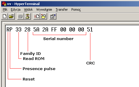
  • Above image link
  • This protocol is serial communication protocol
  • Its developed by Dallas Semiconductor.
Read more… →

Embedded Interface – Touch Keypad

A touch keypad is an input device that allows users to interact with electronic devices by touching designated areas on its surface. It typically consists of a panel with sensitive touch sensors beneath, capable of detecting the presence and location of touch inputs. Touch keypads are commonly used in various electronic devices such as smartphones, tablets, ATMs, point-of-sale terminals, and household appliances like microwave ovens and washing machines. They offer advantages like sleek design, ease of use, and versatility in terms of layout and functionality.

Read more: Embedded Interface – Touch Keypad

TTP226

TTP226 based Module – 1

Here is the Specifications

FeatureDescription
On board 8 key TTP226 capacitive touch induction IC.Allows for capacitive touch sensing with 8 keys.
On board 8-way level indicator.Features an 8-way level indicator on board.
Working voltage2.4 V to 2.4 V
ModulesAllows for setting output mode, key output mode, the longest time, and fast/low power output.
PCB board sizeDimensions: 47.5 mm (width) x 46 mm (height).
Read more… →

Embedded Interface – EEPROM

EEPROM stands for Electrically Erasable Programmable Read-Only Memory. It’s a type of non-volatile memory that can store small amounts of data even when power is removed. EEPROMs are commonly used in applications where persistent storage of configuration settings or small amounts of user data is required, such as in microcontrollers, embedded systems, and electronic devices like USB flash drives and SD cards. Unlike traditional ROM (Read-Only Memory), EEPROM can be electrically erased and reprogrammed multiple times, making it flexible and suitable for applications that require frequent updates to stored data.

Feature

One prominent feature of EEPROM is its ability to be electrically erased and reprogrammed, allowing for multiple read-write cycles. This feature makes EEPROM ideal for storing data that may need frequent updates or modifications, such as configuration settings or user preferences in electronic devices. Additionally, EEPROMs typically offer low-power consumption, fast access times, and compatibility with a wide range of microcontrollers and electronic systems. Moreover, they often have a relatively high endurance, allowing them to withstand many read and write cycles before wearing out.

AT24C128 I²C EEPROM Feature

  • Voltage
    • Low Voltage (1.8v to 3.6v)
    • Standard Voltage (2.7V to 5.5V)
  • Memory
    • 128K (16,384 x 8)
    • 256K (32,768 x 8)
  • I²C Interface (Bi-Directional data transfer protocol)
  • Speed
    • 1MHz(5v)
    • 400KHz(2.7v, 2.5v)
    • 100kHz(1.8v)
  • High Reliablility
    • 1 Million write cycles of endurance
    • 40 years of Data Retention

EEPROM Datasheet

Next Topic

Embedded Interface 7 Segment (Add Soon)
Embedded Interface ADC (Add Soon)
Embedded Interface Button (Add Soon)
Embedded Interface EEPROM (Add Soon)
Embedded Interface LCD (Add Soon)
Embedded Interface LCD HD44780 (Add Soon)
Embedded Interface LED
Embedded Interface MCP23017
Embedded Interface Motor (Add Soon)
Embedded Interface PCF8574 and PCF8574A
Embedded Interface RTC (Add Soon)
Embedded Interface Switch
Embedded Interface Touch Kypad
Embedded Interface RGB LED (Add Soon)

Embedded Interface – RTC

Application

  • Whats-app
    • Every mobile has an in-build RTC. Whatsapp is taking current time from mobile system processor using RTC function and send to WhatsApp server. Once Receptive is online he will receive the  message with a timestamp

Next Topic

Embedded Interface 7 Segment (Add Soon)
Embedded Interface ADC (Add Soon)
Embedded Interface Button (Add Soon)
Embedded Interface EEPROM (Add Soon)
Embedded Interface LCD (Add Soon)
Embedded Interface LCD HD44780 (Add Soon)
Embedded Interface LED
Embedded Interface MCP23017
Embedded Interface Motor (Add Soon)
Embedded Interface PCF8574 and PCF8574A
Embedded Interface RTC (Add Soon)
Embedded Interface Switch
Embedded Interface Touch Kypad
Embedded Interface RGB LED (Add Soon)

Embedded Interface – RGB LED

PWM -Pulse width Modulation

RGB LED


Type of RGB LED


Next Topic

Embedded Interface 7 Segment (Add Soon)
Embedded Interface ADC (Add Soon)
Embedded Interface Button (Add Soon)
Embedded Interface EEPROM (Add Soon)
Embedded Interface LCD (Add Soon)
Embedded Interface LCD HD44780 (Add Soon)
Embedded Interface LED
Embedded Interface MCP23017
Embedded Interface Motor (Add Soon)
Embedded Interface PCF8574 and PCF8574A
Embedded Interface RTC (Add Soon)
Embedded Interface Switch
Embedded Interface Touch Kypad
Embedded Interface RGB LED (Add Soon)

Embedded Interface – Switch


Slide Switch


Rotary Switch


Push Switch

These are either normally on (Push-to-break0, or normally off(Push-to-make). They can be latched, So they stay pressed down after you remove your finger, like the switches on a torch.


Micro Switch


Reed Switch

These are magnetically activated


Next Topic

Embedded Interface 7 Segment (Add Soon)
Embedded Interface ADC (Add Soon)
Embedded Interface Button (Add Soon)
Embedded Interface EEPROM (Add Soon)
Embedded Interface LCD (Add Soon)
Embedded Interface LCD HD44780 (Add Soon)
Embedded Interface LED
Embedded Interface MCP23017
Embedded Interface Motor (Add Soon)
Embedded Interface PCF8574 and PCF8574A
Embedded Interface RTC (Add Soon)
Embedded Interface Switch
Embedded Interface Touch Kypad
Embedded Interface RGB LED (Add Soon)

Embedded Interface – ADC

The analog-to-digital converter (ADC) converts the continuous analog signal into a flow of digital values. To achieve this, the converter must establish the rate at which new digital values sample from the analog signal. This rate is termed the sampling rate or sampling frequency of the converter.

Read more: Embedded Interface – ADC

ADC

A successive approximation ADC uses a comparator to narrow the input voltage range. Digital systems store values in binary format, with resolution usually in bits, often a power of two. Furthermore, one can define resolution electrically and represent it in volts. Consequently, we call the smallest voltage change needed to alter the output code level the least significant bit.

ADC Advantage:

AspectDescription
High PrecisionADCs provide high precision in converting analog signals into digital form, thereby ensuring an accurate representation of the original signal. Consequently, this precision allows for reliable data processing and analysis.
CompatibilityModern digital systems find digital signals more compatible, as they can easily process, transmit, and store them using digital devices. Additionally, this compatibility enhances the efficiency and effectiveness of digital systems in various applications.
Noise ImmunityDigital signals are less susceptible to noise interference during transmission or processing compared to analog signals. Consequently, this leads to better signal integrity and more reliable data transmission in digital communication systems.
Signal ProcessingDigital signals allow for advanced signal processing techniques such as filtering, modulation, and encryption. As a result, this enhances the versatility of digital systems, enabling them to adapt to a wide range of applications and requirements.
Ease of IntegrationADCs can be integrated into various electronic devices, providing a seamless interface between analog sensors or sources and digital processing units. Consequently, this integration enhances the functionality and performance of electronic systems by enabling accurate and efficient conversion of analog signals into digital data.

Disadvantage:

AspectDescription
Sampling Rate LimitationsADCs are limited by their sampling rate, which determines the maximum frequency of signals they can accurately capture. Consequently, inadequate sampling rates can lead to aliasing and loss of signal fidelity, compromising the accuracy of the digital representation of analog signals.
Quantization ErrorDuring the analog-to-digital conversion process, quantization error can occur. Consequently, this can lead to inaccuracies in the representation of the original analog signal, affecting the fidelity of the digital output.
Complexity and CostHigh-resolution ADCs, capable of accurately capturing fine details in analog signals, can be complex and expensive. Consequently, for applications demanding high-speed or high-precision conversion, these ADCs may pose challenges due to their complexity and cost.
Conversion TimeADCs require a finite amount of time to convert analog signals into digital form. As a result, this causes latency in real-time systems or applications that demand rapid signal processing.
Dynamic Range LimitationsADCs have a limited dynamic range, which can affect their ability to accurately capture signals with a wide range of amplitudes. Consequently, this limitation can potentially cause distortion or loss of information in the converted signal, particularly when dealing with signals of varying amplitudes.

Features of ADC

  1. Resolution: This refers to the number of bits used to represent the analog input in digital form. Higher resolution ADCs can represent smaller voltage changes, providing greater precision.
  2. Sampling Rate: The rate at which the ADC samples the analog input signal and converts it into digital form. It is typically measured in samples per second (SPS) or Hertz (Hz).
  3. Input Range: The range of analog input voltages that this can accurately convert into digital values without distortion or clipping.
  4. Accuracy: This refers to how closely the digital output of the ADC matches the true analog input signal.
  5. Speed: The time taken by the ADC to complete one conversion cycle, including sampling and conversion.

ADC Application

ApplicationDescription
Industrial AutomationADCs monitor and control analog sensors like temperature, pressure, and flow sensors in industrial automation systems.
Medical InstrumentationADCs convert signals from medical sensors like ECG or blood pressure monitors into digital data for analysis in medical instrumentation.
Audio ProcessingADCs convert analog audio signals from microphones or musical instruments into digital format for storage or processing in audio applications.
Automotive SystemsADCs are integrated into automotive systems for functions like engine control, airbag deployment, and sensor data acquisition for driver assistance systems.
Communication SystemsADCs convert analog signals, such as voice or data, into digital format for transmission over digital communication networks in communication systems.
Test and MeasurementADCs capture and analyze analog signals with high precision in test and measurement equipment, supporting applications like oscilloscopes and data loggers.
Consumer ElectronicsADCs in consumer electronics, like smartphones and digital cameras, convert various analog signals into digital data for processing or display.
Renewable Energy SystemsADCs monitor and control the generation and distribution of electrical power in renewable energy systems like solar or wind power inverters.

Next Topic

Embedded Interface 7 Segment (Add Soon)
Embedded Interface ADC (Add Soon)
Embedded Interface Button (Add Soon)
Embedded Interface EEPROM (Add Soon)
Embedded Interface LCD (Add Soon)
Embedded Interface LCD HD44780 (Add Soon)
Embedded Interface LED
Embedded Interface MCP23017
Embedded Interface Motor (Add Soon)
Embedded Interface PCF8574 and PCF8574A
Embedded Interface RTC (Add Soon)
Embedded Interface Switch
Embedded Interface Touch Kypad
Embedded Interface RGB LED (Add Soon)

Embedded Interface – Motor

Example

  • DC Motor
  • Stepper Motor
    • Bipor Stepper Motor
    • Unipolar Stepper Motor.
  • Servo Motor


Next Topic

Embedded Interface 7 Segment (Add Soon)
Embedded Interface ADC (Add Soon)
Embedded Interface Button (Add Soon)
Embedded Interface EEPROM (Add Soon)
Embedded Interface LCD (Add Soon)
Embedded Interface LCD HD44780 (Add Soon)
Embedded Interface LED
Embedded Interface MCP23017
Embedded Interface Motor (Add Soon)
Embedded Interface PCF8574 and PCF8574A
Embedded Interface RTC (Add Soon)
Embedded Interface Switch
Embedded Interface Touch Kypad
Embedded Interface RGB LED (Add Soon)

Embedded Interface – LCD

LCD stands for Liquid Crystal Display. It’s a type of flat-panel display technology commonly used in TVs, computer monitors, smartphones, and other electronic devices. This work by sandwiching a layer of liquid crystals between two transparent electrodes and two polarizing filters. When an electric current passes through the liquid crystals, they align to allow varying amounts of light to pass through, creating images or text on the screen. LCDs are known for their sharp image quality, energy efficiency, and relatively low cost compared to other display technologies like OLED (Organic Light Emitting Diode).

Read more: Embedded Interface – LCD

Sure, here are some advantages and disadvantages of LCD displays:

Advantages:

  1. Energy Efficiency: LCDs typically consume less power compared to older display technologies like CRTs (Cathode Ray Tubes), making them more energy-efficient.
  2. Slim Profile: LCD panels are generally thin and lightweight, making them suitable for slim and portable devices such as laptops, tablets, and smartphones.
  3. Sharp Image Quality: LCDs can produce high-resolution images with excellent clarity and color accuracy, providing a visually pleasing viewing experience.
  4. Versatility: LCD technology is versatile and can be used in various applications, including TVs, computer monitors, digital signage, and automotive displays.
  5. Longevity: LCD panels have a relatively long lifespan compared to some other display technologies when properly maintained, providing years of reliable use.

Disadvantages:

  1. Limited Viewing Angles: LCDs may exhibit color distortion or brightness loss when viewed from extreme angles, making them less suitable for applications where multiple viewers may be viewing the screen from different angles.
  2. Potential Motion Blur: Some LCD displays, especially those with slower response times, may suffer from motion blur, resulting in less-than-optimal performance for fast-moving content such as gaming or sports.
  3. Backlight Uniformity Issues: LCDs rely on a backlight source to illuminate the screen, and sometimes there can be issues with backlight uniformity, leading to uneven brightness or “clouding” in certain areas of the display.
  4. Limited Contrast Ratio: While modern LCDs have improved contrast ratios, they may still not match the deep blacks and high contrast levels achievable with technologies like OLED.
  5. Risk of Dead Pixels: LCD panels may develop dead pixels over time, resulting in small, permanently lit or unlit spots on the screen, which can be distracting, especially in high-resolution displays.

Despite these disadvantages, LCD technology remains widely used and continues to be improved upon with advancements in backlighting, panel technology, and image processing algorithms.

Examples

  • Display Character
  • Display String
  • Display Decimal
    • Display one Digit Decimal
    • Display Two Digit Decimal
    • Display Three Digit Decimal
  • Auto scroll Display
  • Blink
  • Cursor On/Off
  • Custom Character
  • Display
  • Hello world
  • Scroll
  • Serial Display
  • Set Cursor
  • Text Direction

Interface with Micro-controllers

Different LCD Displays

  • Nokia 5110 LCD Module with PCD8544 
  • Nokia 6610 
  • OLEDs 
  • 2×16 LCD- hd44780 
  • Nextion Display 

Next Topic

Embedded Interface 7 Segment (Add Soon)
Embedded Interface ADC (Add Soon)
Embedded Interface Button (Add Soon)
Embedded Interface EEPROM (Add Soon)
Embedded Interface LCD (Add Soon)
Embedded Interface LCD HD44780 (Add Soon)
Embedded Interface LED
Embedded Interface MCP23017
Embedded Interface Motor (Add Soon)
Embedded Interface PCF8574 and PCF8574A
Embedded Interface RTC (Add Soon)
Embedded Interface Switch
Embedded Interface Touch Kypad
Embedded Interface RGB LED (Add Soon)

Embedded Interface – 7 Segment Display

Example

  • One 7-Segment Display
    • Display Character
    • Display Decimal
  • Multi 7 Segment Display
    • Display Character
    • Display Decimal

Next Topic

Embedded Interface 7 Segment (Add Soon)
Embedded Interface ADC (Add Soon)
Embedded Interface Button (Add Soon)
Embedded Interface EEPROM (Add Soon)
Embedded Interface LCD (Add Soon)
Embedded Interface LCD HD44780 (Add Soon)
Embedded Interface LED
Embedded Interface MCP23017
Embedded Interface Motor (Add Soon)
Embedded Interface PCF8574 and PCF8574A
Embedded Interface RTC (Add Soon)
Embedded Interface Switch
Embedded Interface Touch Kypad
Embedded Interface RGB LED (Add Soon)

Embedded Interface – Button

Examples

  • LED ON/OFF Using Button
  • Button De-bounce
  • Four Button (UP, DOWN, ENTER, BACK)
    • Set Value By Four_Buttons using 7 Segment Display
    • Set Value By Four_Buttons using LCD Display
  • Matrix Keypad
    • Set Value by Matrix Keypad using 7 Segment Display
    • Set Value by Matrix Keypad using LCD Display
    • Display characters by Matrix Keypad using 7 Segment Display
    • Display characters by Matrix Keypad using LCD Display


Next Topic

Embedded Interface 7 Segment (Add Soon)
Embedded Interface ADC (Add Soon)
Embedded Interface Button (Add Soon)
Embedded Interface EEPROM (Add Soon)
Embedded Interface LCD (Add Soon)
Embedded Interface LCD HD44780 (Add Soon)
Embedded Interface LED
Embedded Interface MCP23017
Embedded Interface Motor (Add Soon)
Embedded Interface PCF8574 and PCF8574A
Embedded Interface RTC (Add Soon)
Embedded Interface Switch
Embedded Interface Touch Kypad
Embedded Interface RGB LED (Add Soon)

Embedded Interface – LED

LED (Light Emitted Diode)

Symbol

How to Identify the LED’s Positive and Negative Leads ?

  • Long lead is positive(+) and small lead is negative(-)
  • Round circle lead is positive(+) and flat lead is negative(-)

LED Chemical Substance

Summary of LED’s Colors and Common Chemistries

ColorWavelengthMaterials
   
Amber605-620 nmGallium arsenide phosphide, Aluminum gallium indium phosphide
Blue430-505 nmIInGaN (Indium Gallium Nitride), Gallium nitride, Silicon carbide, Sapphire, Zinc selenide
Green550-570 nmAluminum gallium phosphide, Gallium nitride
Infra-Red850-940 nmGallium arsenide, AL GaAs (Aluminum Gallium Arsenide)
Red630-660 nmAL GaAs (Aluminum Gallium Arsenide), Gallium arsenide phosphide, Gallium phosphide
Ultraviolet370-400 nmIndium gallium nitride, Aluminum gallium nitride
Violet410-420nm 
Yellow585-595 nmAluminum gallium phosphide, Gallium arsenide phosphide, Gallium phosphide

Light wave length

WaveLenthLED APPLICATION
410nm-420nm(violet)Skin therapy
430nm-470nm(blue)Dental curing instrument
470nm(blue)White LED’s using phosphor, blue for RGB white
520nm-530nm(green)Green traffic signal lights, amber for RGBA white lights
580nm-590nm(amber)Red signal lights, red for RGBA white lights
630nm-640nm(red)Blood oximetry
660nm(deep red)Skin therapy
680nm(deep red)Night vision illuminators and beacons for use with night vision goggles or CCD’S
800nm-850nm(near IR)Photo electric controls
940nm(near IR)Convert illumination CCD based systems

Reference  : http://www.goldwynled.com/knowledge-bank/leds-basics


GLOW LEDs

LEDs ON

LEDs OFF

LEDs Blink

Application

  • Status Indicator
  • WiFi Router Status Indicator (Blink LEDs-Internet Status)
  • Charge level Indication in mobile power-bank [Blink LEDs – Single RGB LEDs or Multiple Color LEDs)
  • Bike Automation
    • Bike Turn Indicator (LED Blink – while turned)
    • Bike Side stand indicator (LED Glow -if Side stand is not took)
  • Car Automation
    • Car Turn Indicator (LED Blink – while turned)
    • Car Door Status indicator(LED Glow -if Door is not close or opened)

LED Examples

  • ON/OFF
  • Blink using the Delay Function
  • Blink using the Timer Function
  • Status Indicator(Using condition Check)Button

Embedded Interface – PCF8574 and PCF8574A I/O Expender

In this article we are discussing Embedded Interface – PCF8574 and PCF8574A I/O Expender.

The PCF8574 device provides general-purpose remote I/O expansion for most micro controllers
families by way of the I2C interface [serial clock(SCL), serial data (SDA)]. 8-bit 2.5- to 5.5-V I2C/SMBus I/O expander with interrupt

The device features an 8-bit quasi-bidirectional I/O port (P0–P7), including latched outputs with high current drive capability for directly driving LEDs. Each quasi-bidirectional I/O can be used as an input or output without the use of a data-direction control signal. At power on, the I/Os are high. In this mode,
only a current source to VCC is active.

Read more… →

Embedded Interface – LCD HD44780

  • HD44780 compliant controllers 16×2 Character LCD is a very basic and low-cost LCD module that is commonly used in electronic products and projects.
  • 16×2 means it contains 2 rows that can display 16 characters.
  • Its other variants such as 16×1 and 16×4 are also available in the market.
  • In these displays, each character is displayed using 5×8 or 5×10 dot matrix.

Experiments

  • Change Cursor Location Based on Key Input

LCD4 Bit Mode Functions

void Lcd4_Clear()   {    Lcd4_Cmd(0x00);    Lcd4_Cmd(0x01);    }    // clear screen 0x01

void Lcd4_DisplayOFF_BlinkON_CursorON()        {    Lcd4_Cmd(0x00);    Lcd4_Cmd(0x0B);    }    // 0x0B

void Lcd4_DisplayON_BlinkOFF_CursorOFF()    {    Lcd4_Cmd(0x00);    Lcd4_Cmd(0x0C);    }    // 0x0C

void Lcd4_DisplayON_BlinkOFF_CursorON()     {    Lcd4_Cmd(0x00);    Lcd4_Cmd(0x0D);    }    // 0x0C

void Lcd4_DisplayON_BlinkON_CursorOFF() {    Lcd4_Cmd(0x00);    Lcd4_Cmd(0x0E);    }    // 0x0E

//void Lcd4_Shift_Left()                      {   Lcd4_Cmd(0x01); Lcd4_Cmd(0x08); }   //  0x18

//void Lcd4_Shift_Right()                     {   Lcd4_Cmd(0x01); Lcd4_Cmd(0x0C); }   //  0x1C


Next Topic

Embedded Interface 7 Segment (Add Soon)
Embedded Interface ADC (Add Soon)
Embedded Interface Button (Add Soon)
Embedded Interface EEPROM (Add Soon)
Embedded Interface LCD (Add Soon)
Embedded Interface LCD HD44780 (Add Soon)
Embedded Interface LED
Embedded Interface MCP23017
Embedded Interface Motor (Add Soon)
Embedded Interface PCF8574 and PCF8574A
Embedded Interface RTC (Add Soon)
Embedded Interface Switch
Embedded Interface Touch Kypad
Embedded Interface RGB LED (Add Soon)