8051 Interface Keypad
In this tutorial, we’ll explore the process of interface a 4×4 or 4×3 matrix keypad with the 8051 microcontroller. Its versatility and ease of interfacing with external peripherals make the 8051 microcontroller a popular choice for various embedded systems. One common peripheral is the keypad, which serves as an input device in numerous applications such as security systems, industrial control systems, and consumer electronics.
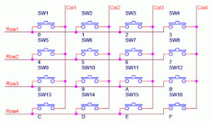
Interfacing a keypad with the 8051 microcontroller involves connecting the keypad’s rows and columns to specific pins on the microcontroller. The keypad typically consists of a matrix of switches arranged in rows and columns. When a key is pressed, it connects a particular row to a specific column, enabling the microcontroller to detect the pressed key by scanning the rows and columns.
We’ll discuss the hardware connections required and the software implementation to read the pressed keys. Additionally, we’ll demonstrate how to display the pressed keys on an LCD (Liquid Crystal Display) connected to the microcontroller, providing a user-friendly interface for input.
By the end of this tutorial, you’ll have a solid understanding of how to interface a keypad with the 8051 microcontroller, enabling you to incorporate user input functionality into your embedded systems projects.

A widely used input device, the keypad, features in various applications like telephones, computers, ATMs, electronic locks, etc., enabling users to input data for further processing. In this setup, we interface a 4×3 matrix keypad, consisting of switches arranged in rows and columns, with the microcontroller. Additionally, we interface a 16×2 LCD to display the output. The concept of interfacing the keypad is straightforward: each key on the keypad has two unique parameters, row and column (R, C). Whenever a key is pressed, the microcontroller identifies the pressed key by detecting its corresponding row and column numbers on the keypad.
4×4 Keypad Internal Circuit Diagram

Image Source
Required Components
- 4×4 Keypad or 3×4 Keypad (Here we will discuss both codes)
- LCD Module (To print the Keys pressed)
- 8051 Micro-controller
8051 Interface 4×3 Keypad Diagram
Image Source

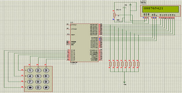
8051 Interface 4×4 Keypad Connections
| Component | Pin | Port |
|---|---|---|
| LCD RS | P3.5 | P3 |
| LCD RW | P3.6 | P3 |
| LCD EN | P3.7 | P3 |
| Data Lines | P2 | |
| Keypad R1 | P1.0 | P1 |
| Keypad R2 | P1.1 | P1 |
| Keypad R3 | P1.2 | P1 |
| Keypad R4 | P1.3 | P1 |
| Keypad C1 | P1.4 | P1 |
| Keypad C2 | P1.5 | P1 |
| Keypad C3 | P1.6 | P1 |
| Keypad C4 | P1.7 | P1 |
8051 Interface 4×4 Keypad C Code
- GitHub Source Code : https://github.com/ArunEworld/Embedded/blob/master/8051-MCU/8051-Interface/8051-Interface-Keypad.c
// www.ArunEworld.com
#include <reg51.h>

#define display_port P2      // Data pins connected to port 2 on microcontroller
sbit rs = P3^2;              // RS pin connected to pin 2 of port 3
sbit rw = P3^3;              // RW pin connected to pin 3 of port 3
sbit e = P3^4;               // E pin connected to pin 4 of port 3

sbit C4 = P1^0;              // Connecting keypad to Port 1
sbit C3 = P1^1;
sbit C2 = P1^2;
sbit C1 = P1^3;
sbit R4 = P1^4;
sbit R3 = P1^5;
sbit R2 = P1^6;
sbit R1 = P1^7;

void msdelay(unsigned int time)  // Function for creating delay in milliseconds.
{
    unsigned i, j;
    for (i = 0; i < time; i++)
        for (j = 0; j < 1275; j++);
}

void lcd_cmd(unsigned char command)  // Function to send command instruction to LCD
{
    display_port = command;
    rs = 0;
    rw = 0;
    e = 1;
    msdelay(1);
    e = 0;
}

void lcd_data(unsigned char disp_data)  // Function to send display data to LCD
{
    display_port = disp_data;
    rs = 1;
    rw = 0;
    e = 1;
    msdelay(1);
    e = 0;
}

void lcd_init()  // Function to prepare the LCD and get it ready
{
    lcd_cmd(0x38);  // For using 2 lines and 5x7 matrix of LCD
    msdelay(10);
    lcd_cmd(0x0F);  // Turn display ON, cursor blinking
    msdelay(10);
    lcd_cmd(0x01);  // Clear screen
    msdelay(10);
    lcd_cmd(0x81);  // Bring cursor to position 1 of line 1
    msdelay(10);
}

void row_finder1()  // Function for finding the row for column 1
{
    R1 = R2 = R3 = R4 = 1;
    C1 = C2 = C3 = C4 = 0;

    if (R1 == 0)
        lcd_data('1');
    if (R2 == 0)
        lcd_data('4');
    if (R3 == 0)
        lcd_data('7');
    if (R4 == 0)
        lcd_data('*');
}

void row_finder2()  // Function for finding the row for column 2
{
    R1 = R2 = R3 = R4 = 1;
    C1 = C2 = C3 = C4 = 0;

    if (R1 == 0)
        lcd_data('2');
    if (R2 == 0)
        lcd_data('5');
    if (R3 == 0)
        lcd_data('8');
    if (R4 == 0)
        lcd_data('0');
}

void row_finder3()  // Function for finding the row for column 3
{
    R1 = R2 = R3 = R4 = 1;
    C1 = C2 = C3 = C4 = 0;

    if (R1 == 0)
        lcd_data('3');
    if (R2 == 0)
        lcd_data('6');
    if (R3 == 0)
        lcd_data('9');
    if (R4 == 0)
        lcd_data('#');
}

void row_finder4()  // Function for finding the row for column 4
{
    R1 = R2 = R3 = R4 = 1;
    C1 = C2 = C3 = C4 = 0;

    if (R1 == 0)
        lcd_data('A');
    if (R2 == 0)
        lcd_data('B');
    if (R3 == 0)
        lcd_data('C');
    if (R4 == 0)
        lcd_data('D');
}

void main()
{
    lcd_init();
    while (1)
    {
        msdelay(30);
        C1 = C2 = C3 = C4 = 1;
        R1 = R2 = R3 = R4 = 0;
        if (C1 == 0)
            row_finder1();
        else if (C2 == 0)
            row_finder2();
        else if (C3 == 0)
            row_finder3();
        else if (C4 == 0)
            row_finder4();
    }
}
Code Explanation
This code appears to be for interfacing a 4×4 matrix keypad with an LCD using an 8051 microcontroller. Let’s break down the code step by step:
Your explanation nicely breaks down the components and functions of the code. Here’s a structured format incorporating your points:
Header Files:
#include<reg51.h>is a header file for the 8051 microcontroller family. It contains definitions of all the register addresses and their bits.
Macro Definitions:
#define display_port P2: This macro defines the port connected to the data pins of the LCD.- We use
sbitdeclarations to declare single-bit variables. For example,sbit rs = P3^2;declares the RS pin of the LCD connected to pin 2 of port 3.
Delay Function:
void msdelay(unsigned int time) {
    unsigned i, j;
    for(i = 0; i < time; i++)
        for(j = 0; j < 1275; j++);
}
- This function creates a delay in milliseconds, commonly used to handle timing requirements in interfacing with peripherals.
LCD Control Functions:
void lcd_cmd(unsigned char command) {
    // Sends command instructions to the LCD
}

void lcd_data(unsigned char disp_data) {
    // Sends display data to the LCD
}

void lcd_init() {
    // Initializes the LCD
}
lcd_cmd(unsigned char command): Sends command instructions to the LCD. Commands are sent by setting appropriate pins (rs,rw,e) and then setting the data on the data pins (display_port).lcd_data(unsigned char disp_data): Sends display data to the LCD. Similar tolcd_cmd()but setsrsto 1 to indicate data transmission.lcd_init(): Initializes the LCD by sending a sequence of commands to set it up, such as configuring it for 2 lines, 5×7 matrix, turning on the display, and clearing the screen.
Keypad Row Finder Functions:
void row_finder1() {
    // Function for finding the row for column 1
}

// Functions for finding the row for column 2, 3, and 4
row_finder1(),row_finder2(),row_finder3(), androw_finder4()are functions to find the row corresponding to each column of the keypad. They scan each row by setting them to 1 and columns to 0, then check which row is active by observing which row pin goes low, and accordingly display the pressed key on the LCD.
Main Function:
void main() {
    // Initializes the LCD and continuously scans the keypad
}
main(): Initializes the LCD and then enters an infinite loop where it continuously scans the keypad. It sets one column at a time to 0 and scans the rows to find the pressed key using the row finder functions. Once a key is found, it displays it on the LCD.
Your explanation covers the key aspects of the code comprehensively!
This code demonstrates how an 8051 microcontroller interfaces a keypad with an LCD, enabling it to display keypad input on the LCD screen.
8051 Keypad Interface Explanation
Initially all the rows are set to zero (‘0’) by the controller and columns are scanned to check if any key is pressed. In case of no key is pressed the output of all columns will be high (‘1’).

